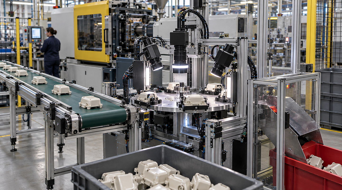
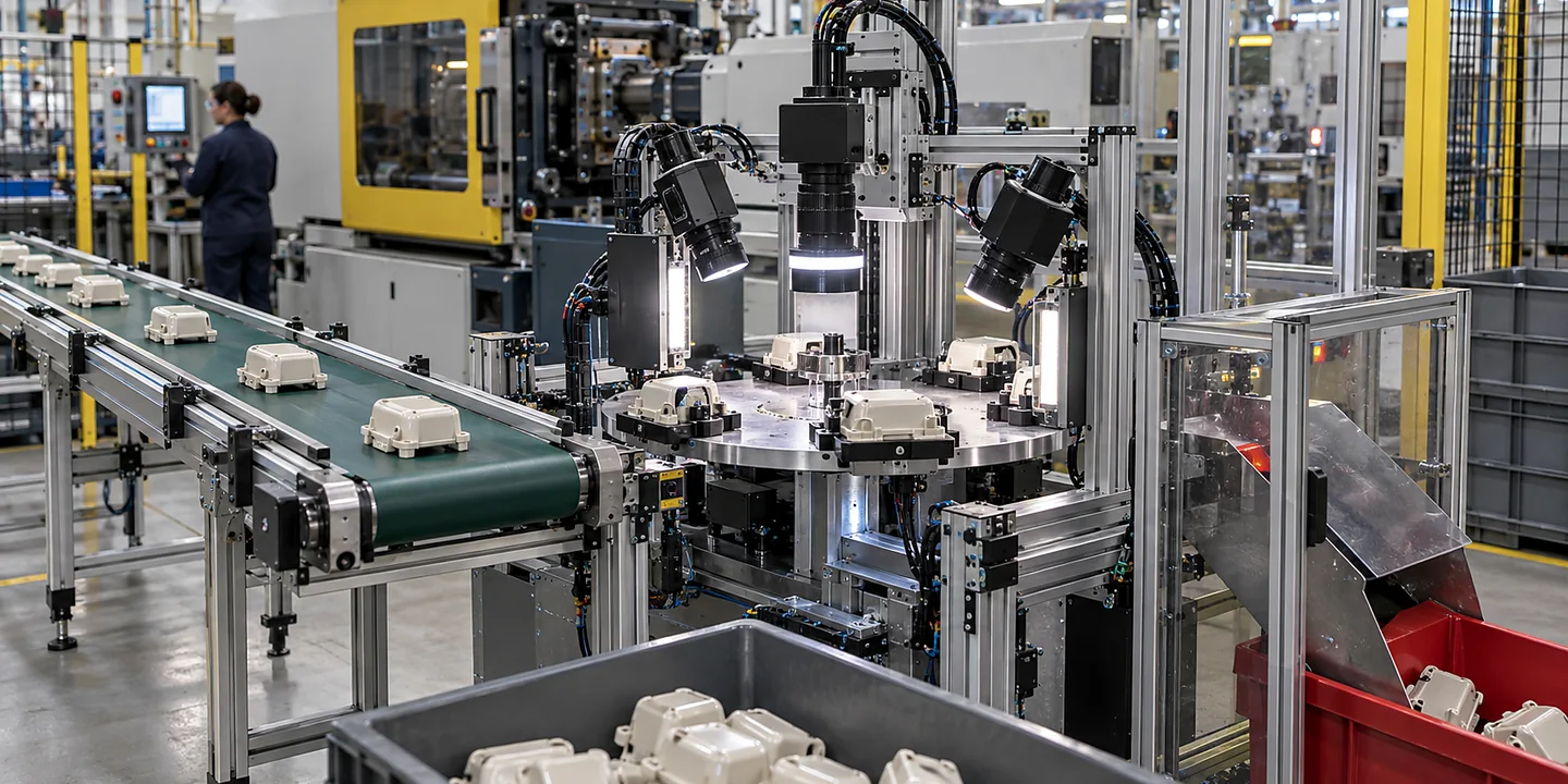
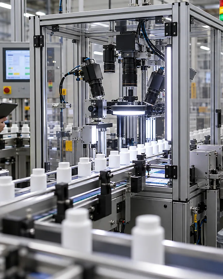
Surface inspection cameras classify visible features against an agreed acceptance boundary. The first task is to make the relevant defect distinguishable from normal finish, texture and reflections; camera choice follows the sample, viewing and lighting trial.
Speak directly with Oxford Vision Systems about visible surface-defect inspection.
Quick answer
Which camera and lighting approach should we trial for our surface defects?
Define the unacceptable defect types and collect real samples near each acceptance limit. Include normal changes in texture, finish and part position. Compare candidate views and lighting on that sample set, recording which surface areas are covered and how uncertain results will be handled in production.
Application decisions
Prove defect visibility before specifying a camera
Decision 1
Define each unacceptable surface feature
Describe the scratch, mark, contamination or finish change to detect, including its location and acceptance boundary. Supply photographs and physical examples of marginal cases. “Any defect” is not a testable requirement when ordinary surface variation is still undefined.
Decision 2
Collect acceptable variation as well as defects
Include changes in colour, texture, coating, supplier batch and part position that are permitted in production. A trial using only one perfect part can overstate capability. Keep the reason each sample is acceptable or unacceptable alongside the sample.
Decision 3
Map the visible inspection area
Identify every surface that needs checking and what hides it in the normal presentation. Consider whether additional views or controlled rotation need investigation. An unseen feature cannot be judged from a single image, and coverage should be stated explicitly in the trial report.
Decision 4
Compare lighting and viewing conditions
Trial the sample set under candidate illumination and camera positions. Include reflections, ambient-light changes and movement expected on the line. Select the method that separates the required feature consistently, rather than judging an attractive demonstration image alone.
Decision 5
Choose rules or AI after the optical trial
Where fixed features can describe the defect, conventional image tools may be appropriate; variable appearance may justify assessing an AI approach. Compare both against held-out production examples and agreed errors. Neither method removes the need for controlled images and representative samples.
Decision 6
Define uncertainty and line response
Record false accepts, false rejects and cases outside the proven inspection range separately. Decide how uncertain products are controlled and how the correct part reaches rejection or review. See the surface inspection acceptance guide for challenge planning.
Applications
Stable in-line viewing or a variable retrofit?
A dedicated station can control viewing and lighting around one presentation. A retrofit or changing product range needs the limits of each view, recipe and surface condition established before capability is accepted.
Collect acceptable, faulty and borderline parts with the required decision recorded.
02
Prove optical contrast and coverage
Assess lighting, viewing position and presentation against the required surfaces.
03
Evaluate the inspection method
Compare decisions on independent examples under the intended production conditions.
04
Challenge tracking and rejection
Check unresolved results, recipe changes and physical control of failed parts.
Practical decision guide
Read a surface-inspection trial without hiding the difficult defects
A single overall percentage can conceal the result that matters most. Separate the sample groups, identify which were used to adjust the inspection and show how the finished setup behaved on a different challenge set.
Keep the two error counts distinct
In an illustrative trial, two missed faults among 20 known defective parts and five rejected parts among 100 accepted parts are different findings. Record both counts and their denominators. Neither this small example nor a zero-error run establishes performance on every future part; the sample coverage and production conditions remain part of the result.
Break the result down by the actual fault classes
Keep scratches, stains, missing features or other agreed defects separate where the quality decision differs. Also distinguish relevant finishes and product variants. A method that works on one colour or texture should not receive an undifferentiated pass for another group that was barely represented.
Do not score a tuning image as an independent challenge
Document which examples influenced references, thresholds or training. Reserve separately classified examples to challenge the completed configuration. When an unexpected sample leads to a change, record that event and repeat the relevant challenge rather than quietly treating the revised result as the original test.
Compare the production consequence as well as the image
Record uncertain results, unavailable views and the actual hold or reject action. Link retained evidence to an identified sample and recipe. The surface inspection acceptance guide provides the next place to agree the site-specific sample plan.
Important limits
Know what needs a separate check
A camera can only assess a property made visible and repeatable by the inspection setup.
Sample diversity and marginal cases determine how meaningful a feasibility result is.
Visual inspection does not replace hidden, destructive, functional or statutory tests.
Your final solution for visible surface-defect inspection must reflect the law, current standards and site-specific risks that apply to your installation.